Installation Guide
Model: ONE-1P-6K-A
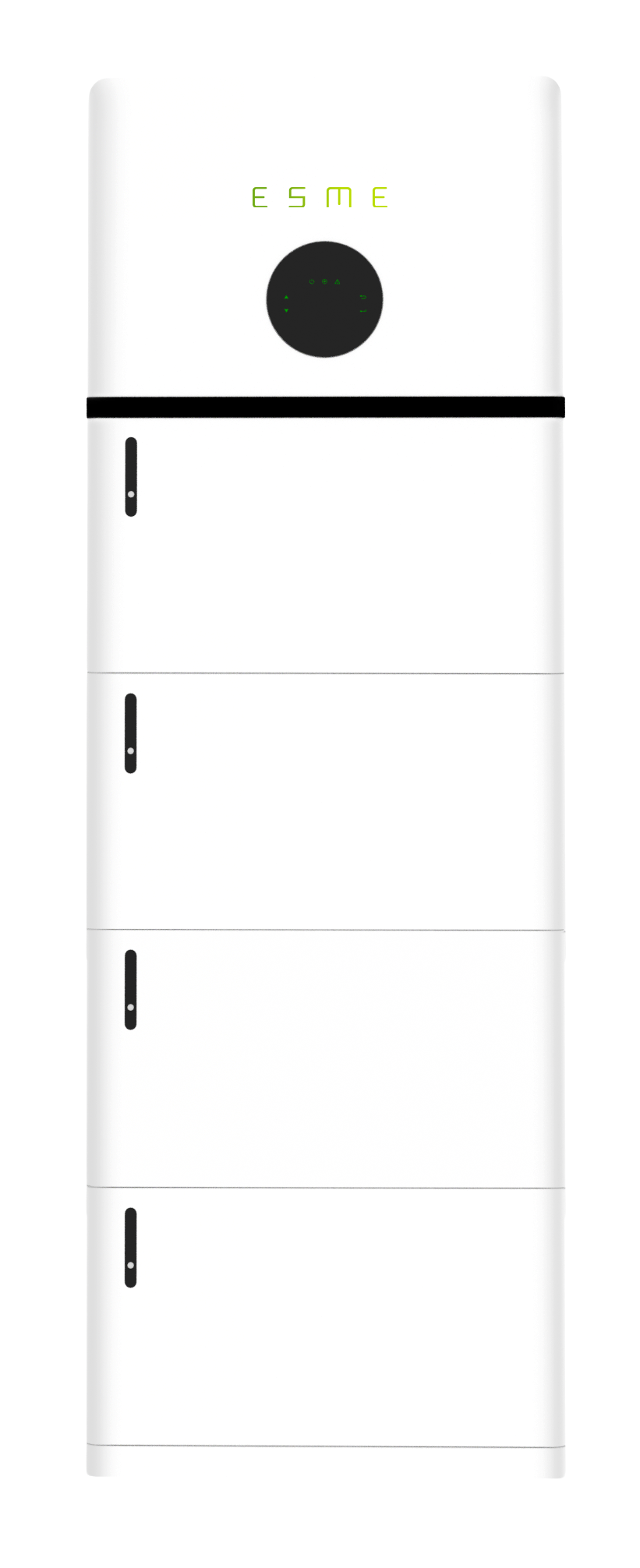
Installation of ESME Power Tower
Packing Contents
On receiving the products, please check to make sure the packaging and all components are not missing or damaged. Please contact your ESME directly for support if there is any damage or you are missing components.
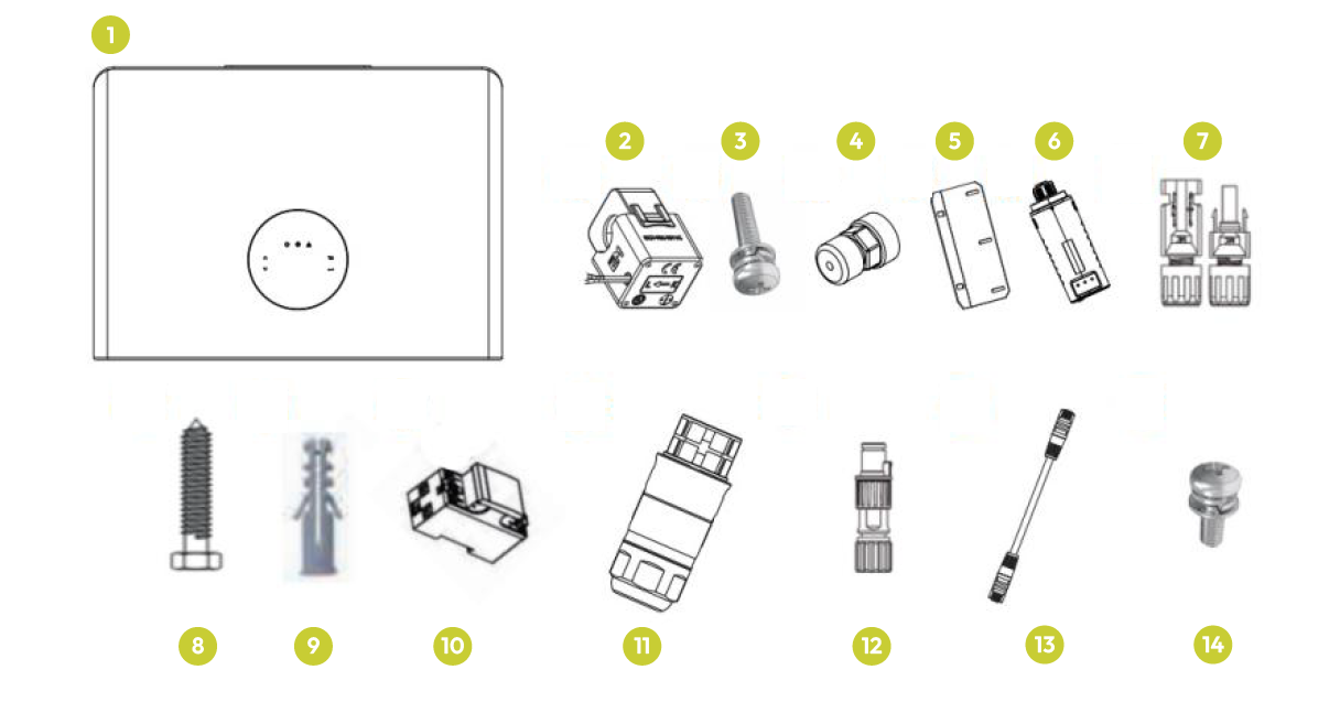
Inverter
1. Hybrid Inverter (x1)
2. CT Clamp (x1)
3. M4*12 Wall Mounting Bracket (x3)
4. Communication Connectors (x1)
5. Wall Mounting Bracket (x1)
6. Data Logger (x1)
7. DC Connector Set (x1)
8. M8*50 Mounting Bracket Screw (x2)
9. M10*50 Rawl Plug (x2)
10. Smart Meter (Optional) (x1)
11. AC Waterproof Cover (x2)
12. Meter Connectors (x1)
13. Communication T568B (x1)
14. M6×12 Security Screw (x1)
Battery
1. Battery (x1)
2. M6*12 Wall Mounting Screw (x2)
3. M10*50 Rawl Plug (x2)
4. M6*12 Connection Screws (x4)
5. M6×12 Security Screw (x1)
6. Wall Mounting Bracket (x1)
7. Battery Mounting Bracket (x1)
Base
1. Base (x1)
2. M10*50 Rawl Plug (x2)
3. M6×50 Mounting Screw (x2)
Installation of Batteries and Inverter
Make sure that the installation location meets the following conditions:
The floor is flat and level.
There are no flammable or explosive materials nearby.
The ambient temperature is between 0°C and 55°C.
Humidity is maintained at 15% - 85% (RH) (no condensing);
The distance from any heat source, such as a radiator, is more than 2 meters.
The distance from the inverter's air outlet is more than 0.5 meters.
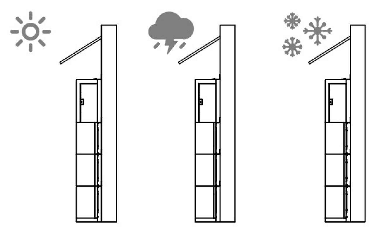
The installation areas shall avoid direct sunlight.
There are no mandatory ventilation requirements for the battery module, but please avoid installation in confined areas. The aeration shall avoid high salinity, humidity or temperature.
Please install the battery system on a foundation about 30cm above the ground. The foundation shall bear a load of 400 kg.
Outdoor installation requires a protective hood above the battery to reduce the impact of rain, snow and strong ultraviolet rays.
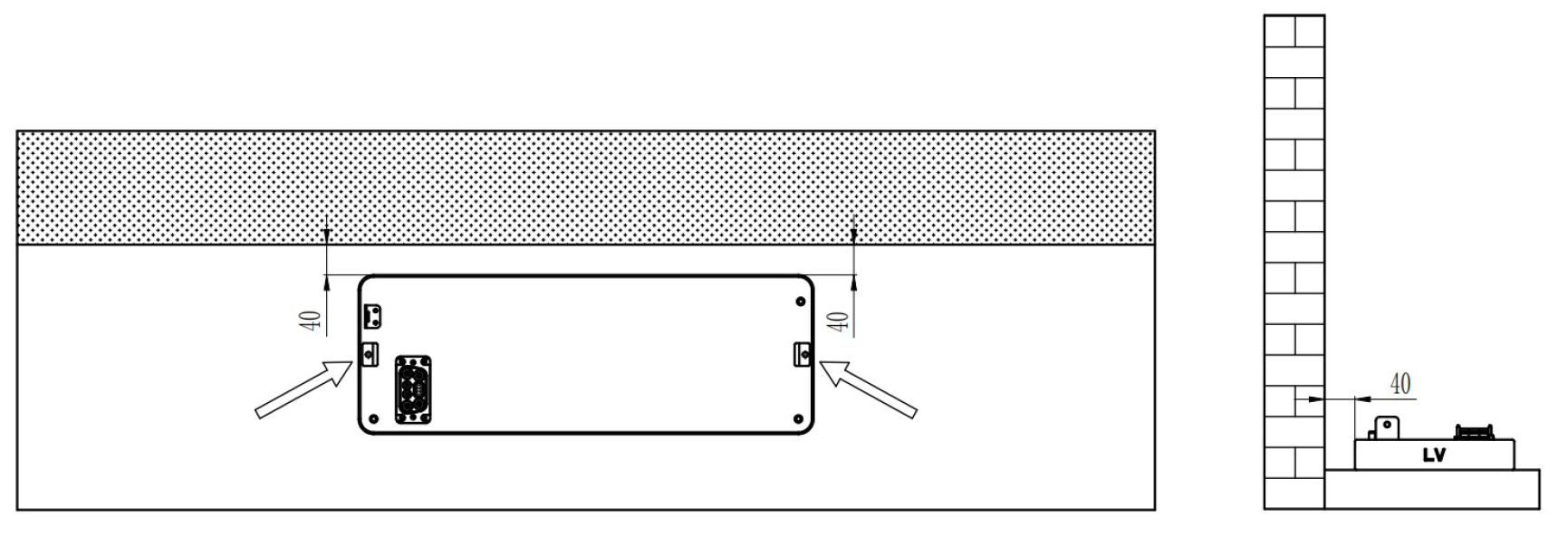
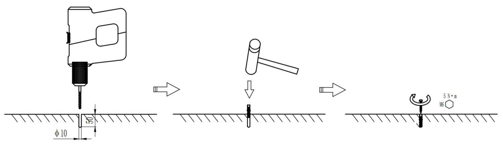
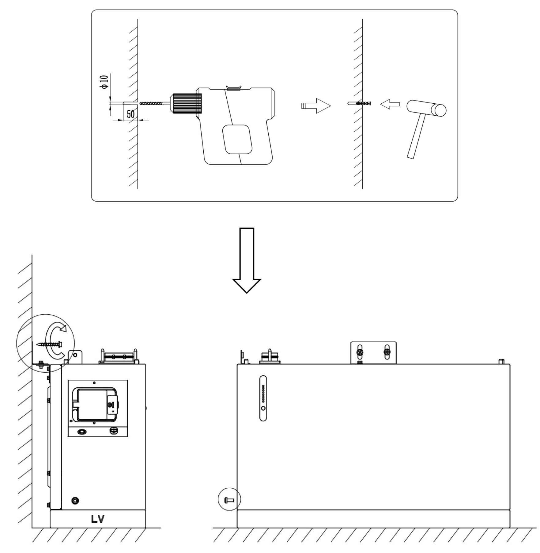
Step 1
Make sure the base is on level ground and 40mm from the wall. Mark the base holes and #10 drill to a depth of 50mm.
Use Rawl Plugs and M6 bolts to secure the base plate to the ground.
Step 2
Drill holes to the marked positions on the ground, and fix the base according to the instructions below.
Step 3
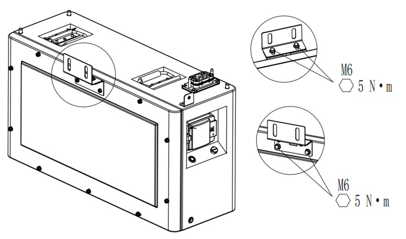
Install the wall mounting bracket and battery mounting bracket on the battery.
Step 4
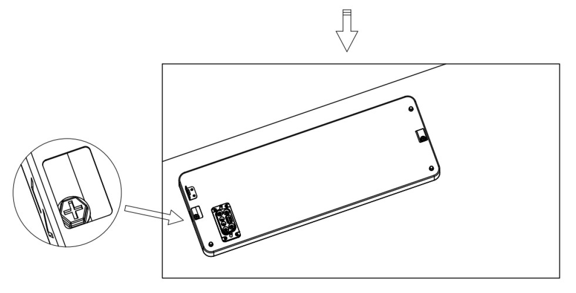
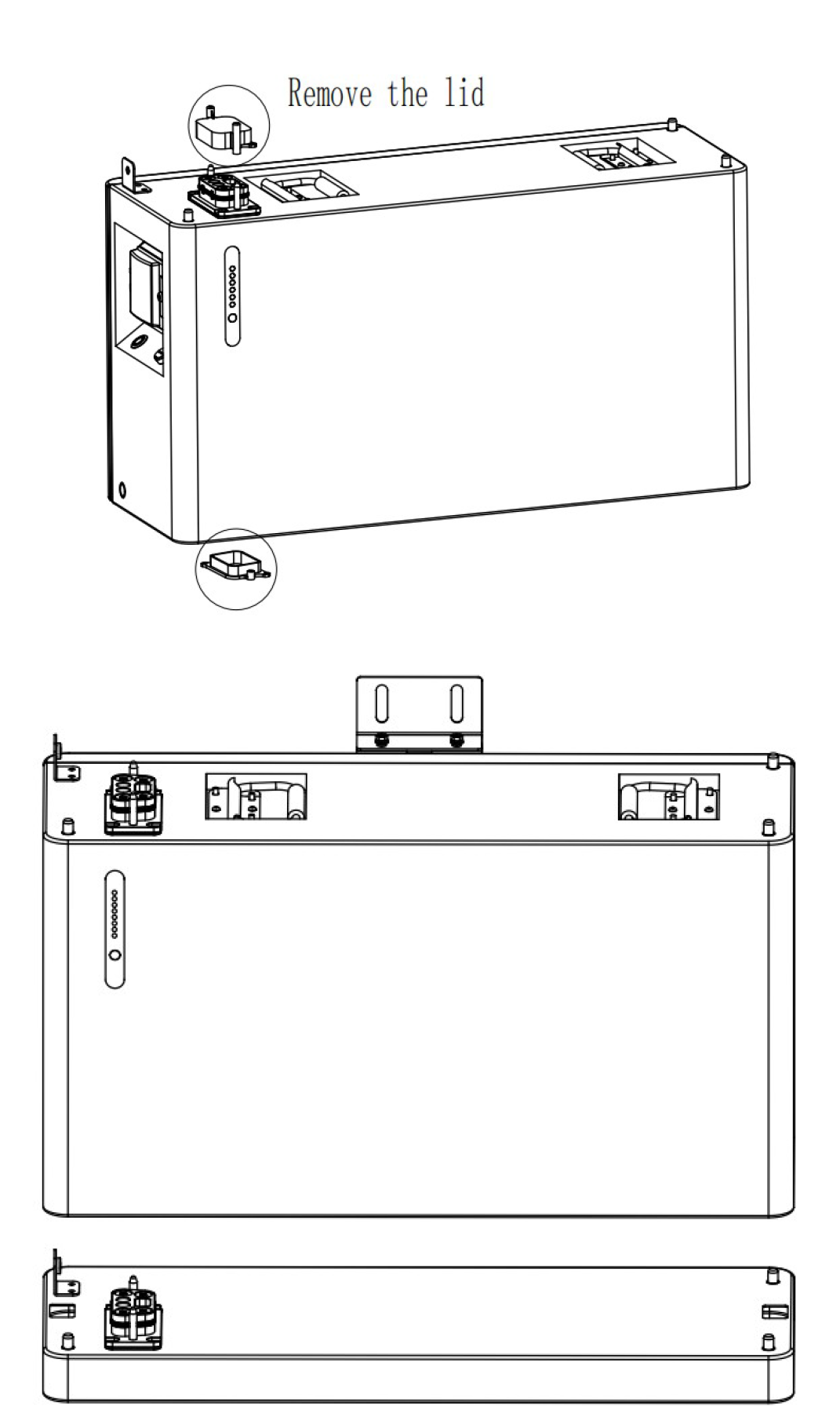
Install the first layer PACK and the second layer PACK on the base, install the wall fasteners, and mark the positioning centre with a marker. In particular, the dust cover and the connector needs to be removed before stacking the PACK.
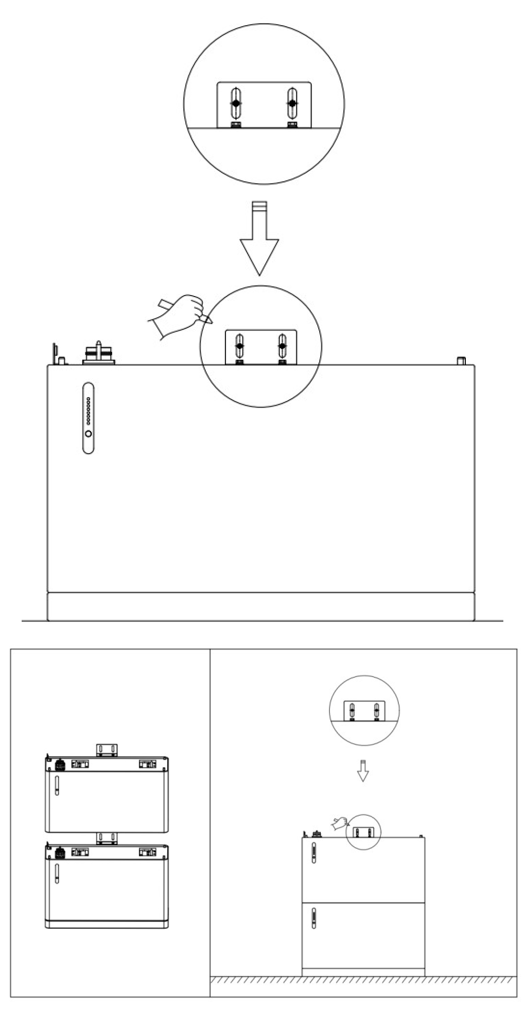
Step 5
Remove the first battery and the second battery to mark the other layers of the battery stack with the positioning plate according to the first and second layer of battery positioning points. Move the positioning plate up to mark the fourth battery positioning points. Mark the fifth battery pack in the same way.
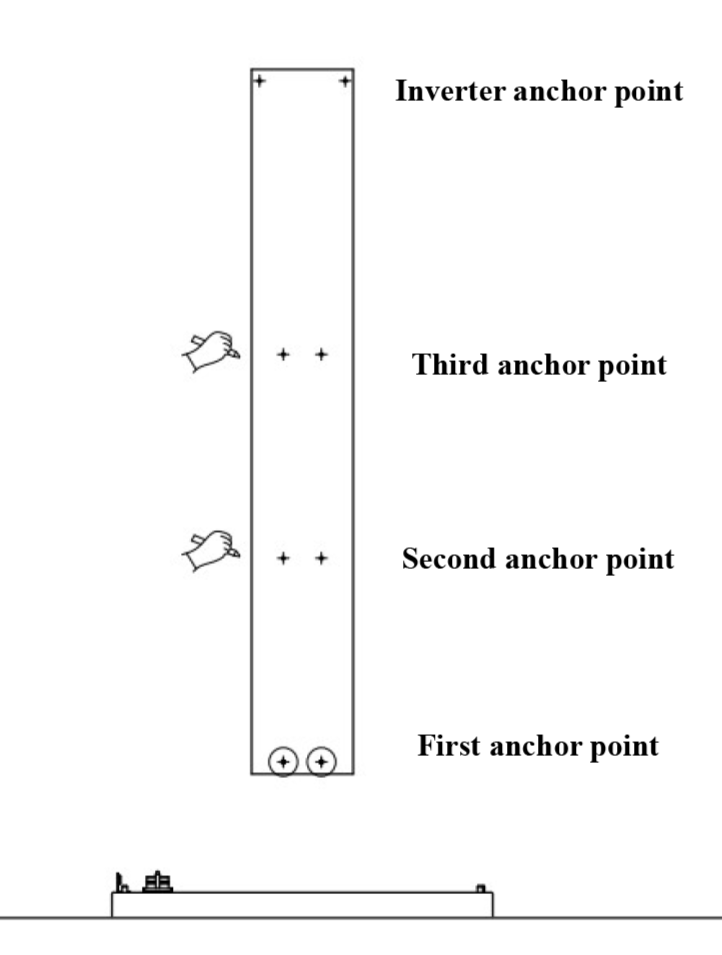
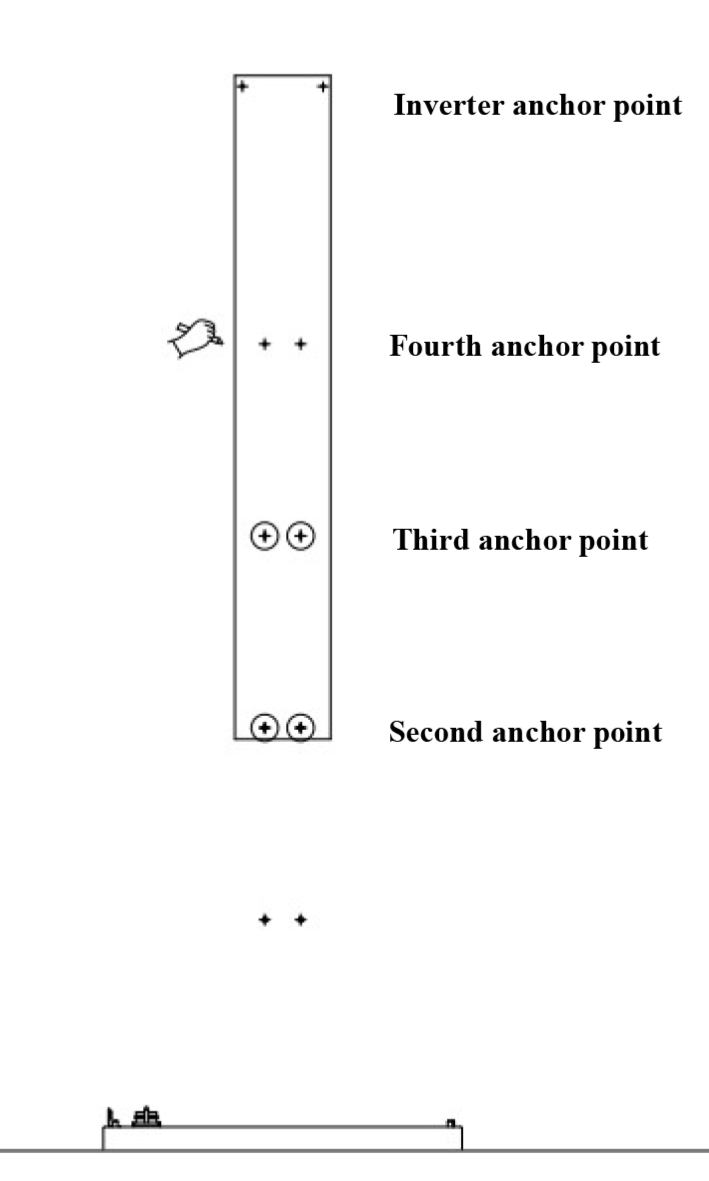
Step 6
Drill the hole according to the anchor point and install the plastic expansion tube. Fix the battery to the wall with fixings, while tightening the side screws of the battery according to the diagrams below to make the pack tightly connected.
Step 7
Follow step 4 to stack the second battery on top of the first, and secure the second layer of battery according to Step 6.
Then repeat the steps to stack and secure the third, fourth, and fifth layers of batteries.
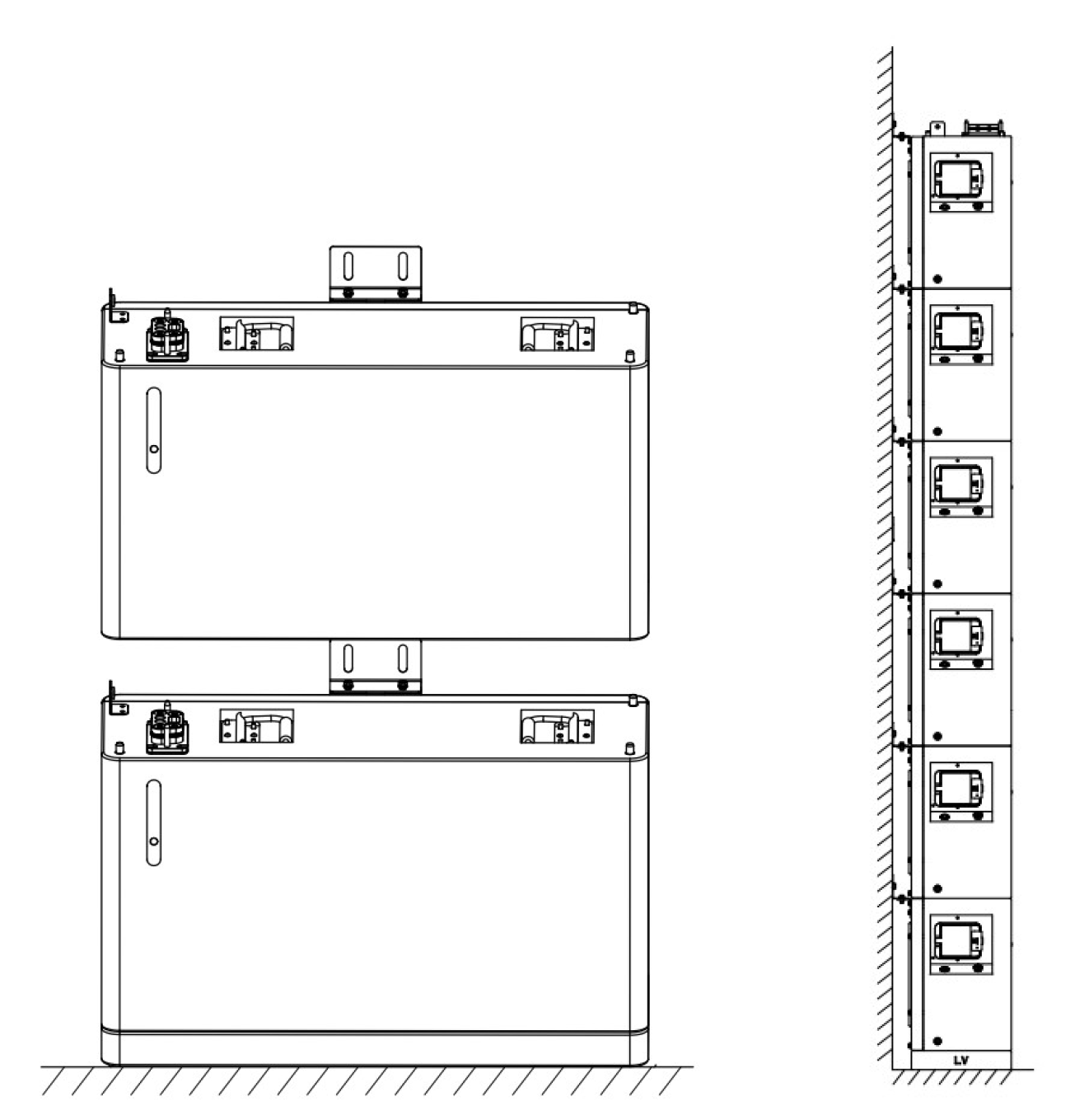
Step 8
Stack the inverters with the uppermost battery as shown in the diagram below. Keep the upper and lower connectors aligned to complete the battery stack, and then secure them with the screws shown in the figure. Finally, fix the inverter to the wall with the fixed parts, and fix the screws on the upper and lower sides.
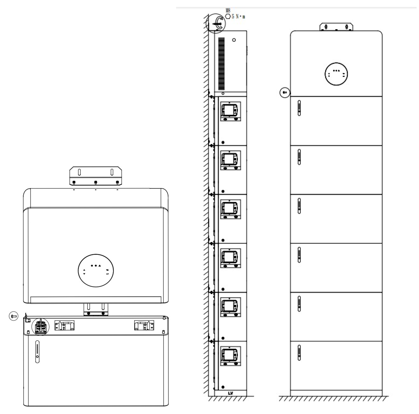
Battery Stack and Inverter installation is now complete
The following instructions relate to the wiring.
Inverter Wiring
The diagram shows the side of the inverter and the required connections.
Note; PV and DC switch are only required if connecting to the customer’s existing photovoltaic panels.
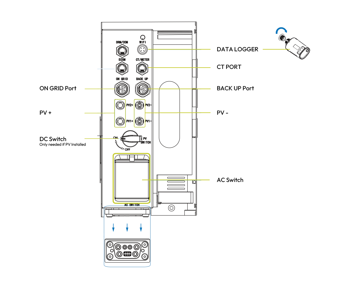
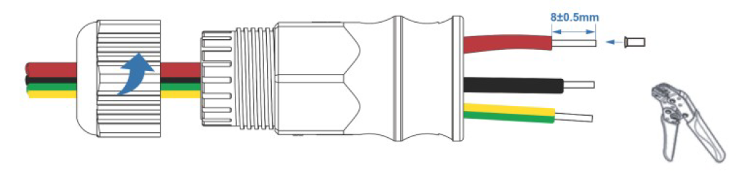
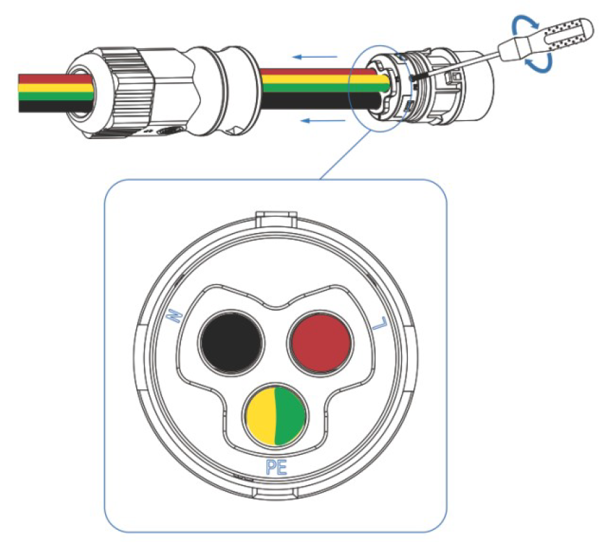
Step 1
Wire grid connection as below. Tighten the cable to the connector with a screwdriver. The AC cable needs to pass through the holes on the back of the inverter prior to fixing. After the wiring cover is connected and locked, it should be pulled to secure the fastening.
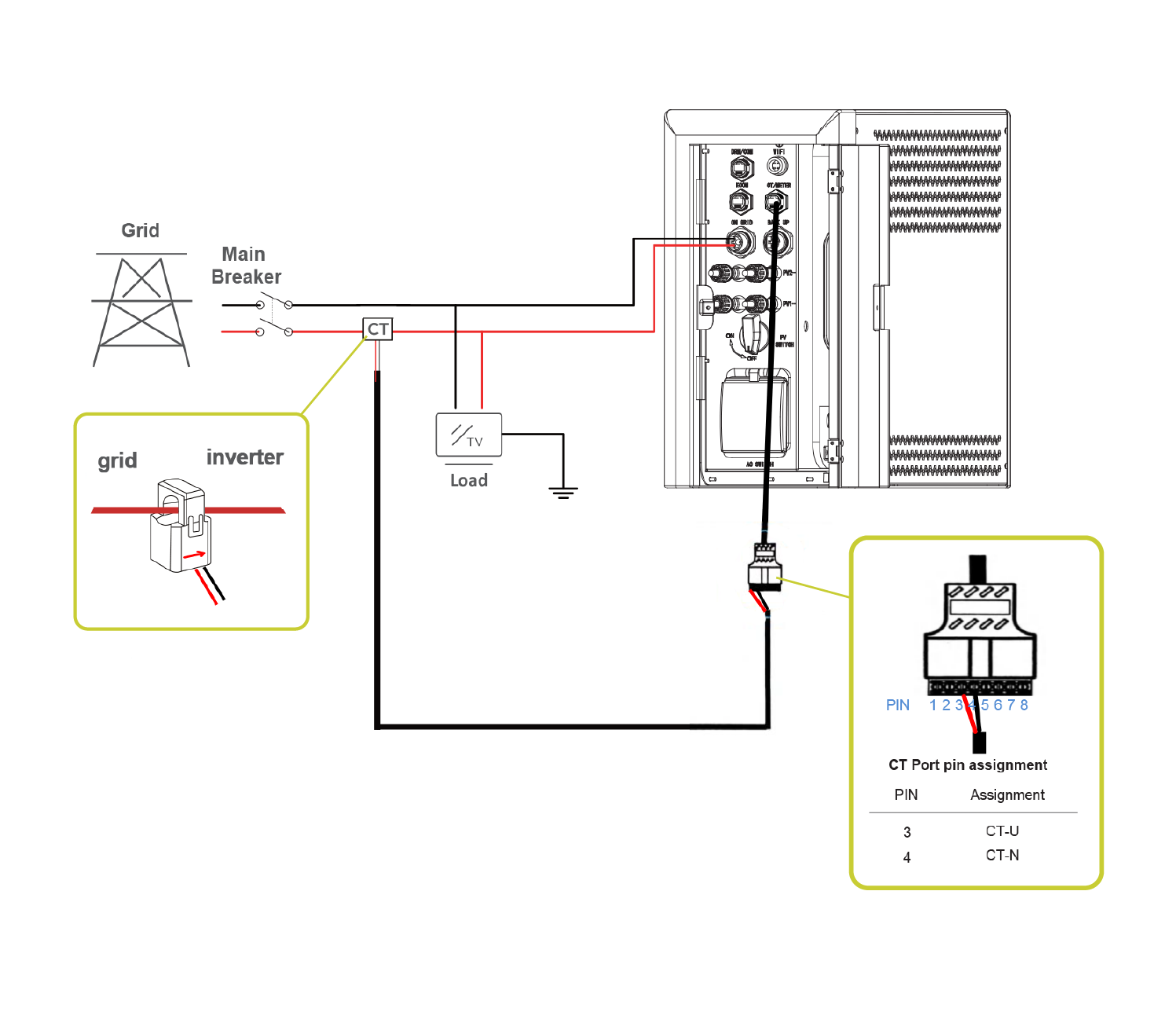
Step 2
CT Clamp connection. Particular attention should be paid to the direction of the arrow on the clamp and the correct pin assignment. The CT Port connector is connected to the Inverter using an Ethernet cable supplied. The inverter end of the Ethernet cable should be covered with a waterproof connector.
Sign in with the ESME App
The ESME App is available to download on Apple or Google. Use Apple or Google ID to complete the sign-in. Connection to the installation will already be configured prior to the installation being completed. Data will be visible in the app within an hour or two.